M14 Engine modification
to help reduce the possibility of Hydraulic Lock.
The fitting of an Intake Drain kit, to help reduce the accumulation of oil
in the lower cylinders, is very desirable. This sketch shows a simple intake
drain kit
for the M14 engine made from off the shelf AN fittings available from almost any
aircraft supply house. The total cost, (not including labor) is less than $100.
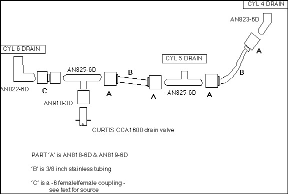
** Errata **
The part labeled AN910-3D in the above diagram should be AN910-2D
Parts List:
|
Qty |
Description |
|
4 |
AN818-6D Nuts |
|
4 |
AN819-6D Sleeve |
|
2 |
AN825-6D Flared
Tee |
|
1 |
AN822-6D 90°
elbow |
|
1 |
AN823-6D 45°
elbow |
|
1 |
AN910-2D
Coupling (Yes it is -2D NOT -6D) |
|
1 |
Curtis drain
valve (1/4" NPT) CCA1600 |
|
1 |
Female/Female
flared coupling * |
|
3' |
3/8" Stainless
steel tubing |
* Few aircraft supply companies stock this part but we have found it
in several racing car catalogs.
Our usual source is:
Pegasus Auto Racing Supplies at
1-(800)-688-6946.
They refer to it as a "Female swivel coupling, AN to AN".
Their part number is 3238-06
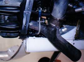
Procedure
- Remove all three drain plugs from the lower intake tubes.
- Drill a 7/16" dia. hole through the center of each plug.
- Tap the holes for a 1/4" NPT (tapered pipe thread).
- Screw an AN822 -6D (90° elbow) fitting into one of the
plugs and screw it into the intake tube of cylinder number 6. (7
o'clock, viewed from the front)
- Screw an AN825-6D (Tee) fitting into the second plug and
install it in the intake tube of cylinder number 5.
- Screw an AN823-6D (45° elbow) into the third drain plug and
install it into the intake tube of cylinder number 4.
- Using the proper flaring tool and two AN818/819-6D 'B'
nuts, make up a tube of the proper length to join the fittings from
cylinders 4 and 5.
- Turning to cylinder 6, screw the female/female union onto
the 90° elbow already installed in the intake tube. Into the other
side of the union, screw one arm of a Tee fitting with the side arm
facing downwards.
- Make up a second tube with AN818/819-6D fittings to run
from the other end of the Tee, under the front of the carburetor, to
the Tee fitting installed in cylinder 5.
- Screw an AN910-3D coupling onto the bottom of the Tee
fitting and into the other end of the coupling, fit the Curtis drain
valve.
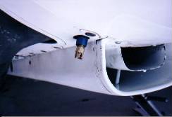
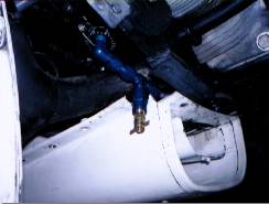
- Finally, make the required cut-out in the cowling to allow
the drain valve to protrude just enough to operate.
Operation
After stopping the engine, open the drain valve and hang a container
on it to catch the oil. If you paint the container red, you will be less likely
to forget to remove it and to close the valve before your next flight!
This simple modification WILL NOT ELIMINATE HYDRAULIC LOCKs in the
engine, but it will make them less likely. It is still essential that the
propeller be rotated in the (in the normal (running) direction before each start
to check that there is no oil in the cylinder head.
Here are some pictures of the finished installation (on an Su31X)